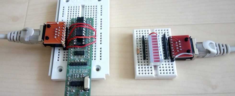
With tool-free connectors, network cables can be crimped without any special pliers. We explain how this works in Make 1/22 – as well as the structure of the network tester that we made to check. It consists of a transmitter and a receiver module, which are connected via the network cable to be tested. An LED display on the receiver side shows whether the connections are ok. On the transmitter side, we use the Nano Ax board, which is exclusive to the Make Picaxe Special, along with the Picaxe 14M2 chip.
The scope of delivery of the booklet includes the Picaxe chip 08M2, which can also be installed in the network tester. However, since it has too few pins for this project, the I2C port expander module CJMCU-2317 required, which contains an MCP23017 chip and provides 16 pins as inputs and outputs.

There is more on the subject in issue 1/22 of Make.
Insert port expander
In the port expander, we first solder a 10-pin header on the side with the I2C pins SDA and SCL so that the pin labels face up when the module is plugged into the breadboard. Also solder a 9-pin header into pads A0 to A7, whereby the ninth pin protrudes and is connected to solder pad B7 with a piece of wire.

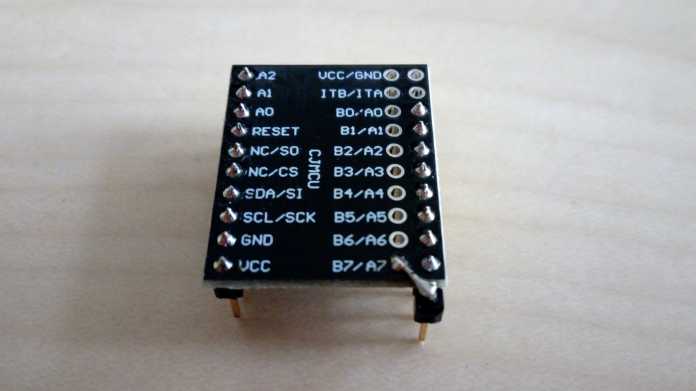
The ninth pin of the pin strip on the right protrudes and is connected to solder pad B7.
The I2C pins SDA and SCL of the port expander are connected to pins C2 and C1 of the Picaxe-08M2. GND and VCC are then plugged into two unused pins and are connected to GND and 5V via jumpers. For reasons of space, we only plugged the Nano-Axe-Board into the breadboard with the pin strip PL4, the other side is not required. The MCP23017’s eight output pins, A0 to A7, are arranged side by side on the CJMCU-2317 board. B7 of the module is also required for the shield.
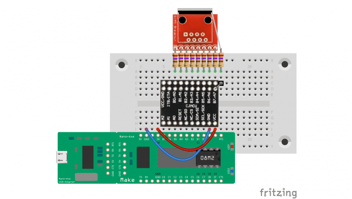
The (white) pin designations for the Picaxe-20M2 are printed on the Nano-Axe board. In the circuit diagram, information for the Picaxe-08M2, pins C0 to C5, is added in white.
Adjust source code
The source code of the Picaxe 08M2 network tester largely corresponds to the version presented in the magazine. For the use of the port expander, an I2C initialization function required. In addition, LED1 to LED9 are included symbol are defined as bit variables that correspond to the I/O pins of the MCP23017 in a 16-bit word. Bit0 corresponds to GPIOA0, Bit7 GPIOA7 and Bit15 GPIOB7. These bit variables are in the byte variables LEDS_A and LEDS_B. The functions setLed and clearLed then describe the corresponding bit variable and write the values of LEDS_A and LEDS_B per I2C to the MCP23017.


Known error
The test has shown that the MCP23017 no longer works correctly in the event of a “short circuit of two wires in the network cable”. After eliminating the short circuit, a power-on reset may be necessary. The reason may be that the GPIOs can only supply relatively little current (less than 5 mA) when the level is high, and the MCP23017 thus gets out of step when it is overloaded.
(hch)